Once upon a time before the age of cellphones, there were things called "landlines". During these dark ages, you had to be at home to make or receive calls - life was hard but people somehow managed to survive.
In the early 2000s, I moved into a condo building that had a telephone entry system that relied on landlines. At some point I got tired of paying AT&T $50/month for a landline and started looking into VOIP solutions. Why not have the the callbox dial my cellphone? Cell reception was awful in my area no matter the carrier and I'd often miss calls or be unable to make them. Enter Ooma. I bought their very first system, hooked it up to a cordless landline system and life was good. I was saving $50/month and telling AT&T to screw off was immensely satisfying.
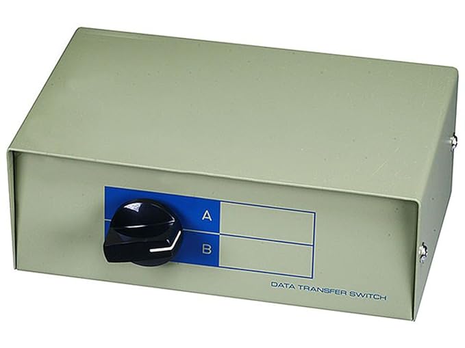
Then the random calls at 3am started. I live in an area where many "interesting" characters are around and some of them figured out that many residents would buzz them into buildings without verifying who they were, giving them free rein to steal anything they could. Ooma wanted to charge $15/month for their 'premier' service which I had no use for other than a do-not-disturb feature. After thinking about it some, I bought this:

Solid metal construction + 80s aesthetic = WIN! Input A went to the landline while input B sat empty as my do-not-disturb option I'd flip to when going to bed.
I was pretty satisfied until I realized I'd often forget to switch the input back to A, causing me to miss calls/deliveries. So I decided to open it up to see if there was any way to hack a reminder or notification. Inside I found a mess of wires connected to the selector knob:

Each input/output jack had 6 wires coming out of it. The selector knob had 24 leads with 6 completely empty/unused. After tracing the wires, I noticed that the leads were connected in blocks of 3 like so:

Using a multimeter, I confirmed connectivity between the A/B lead and the I/O lead depending on the selector knob position. I decided to try and mount a LED indicator. I needed a power source and initially thought of batteries but decided USB would be better since it's only 5 volts and I have adapters all over the damn place.
Parts needed:
- LED
- LED holder
- Resistor (1/8 watt, 180 ohm because that's what googling told me to use)
- USB Panel Mount
Since a LED only has two leads, all I needed to do was hook up the power to 2 unused I/O leads and the LED to 2 unused B leads. After cutting the male USB-A head off the panel mount and stripping the wires, I soldered the wires as below:

Through Google, I learned that the longer leg of the LED is the positive lead and that the resistor can go on either lead. I chose to put it on the positive.
Drilling a hole in the front of the switchbox was easy but using a rotary tool to cut a hole for the USB panel mount was a bit messy:

View of the finished inside:

The end result:

The LED is bright enough to see clear across the room so it's now impossible to forget when the phone line is disabled :D